
3D and GPR
The GPR permits to obtain a linear image of anomalies under the surface of the ground or water, as well as other centres, such as concrete, asphalt or wood. Thus, we obtain a two-dimensional cross-section XY, where X is the distance made, while Y is the time calculated into the depth.
It is also possible to obtain a three-dimensional model of an object in the ground, for example technical infrastructure (pipes, cables, culverts, etc.) by putting together a number of two-dimensional profiles, carried out subsequently in same time intervals. Owing to the newer software, we can obtain such effect by carrying out the survey by means of a broken line of an arbitrary shape with the usage of a GPR connected to a GPS device. The three-dimensional solid obtained in this manner can be rotated, sliced over a selected axis. Furthermore, we can change the coefficient of transparency in order to view only selected signals.
This technology works perfectly in archaeology or building engineering and environmental protection (establishing geometry of waste storage).
The three-dimensional GPR technology allows for a correction of underground infrastructure maps and lowering the number of survey boreholes, because the lithological structure and technical infrastructure are clearly visible. Often, two or three boreholes are sufficient to precisely identify the strata and take samples for physical and chemical tests of the ground.
The manner of creating 3D solids and the ready result in the form of a projection presenting the layout of pipes was shown beside.
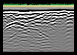
The 2D profile – the GPR readout without processing
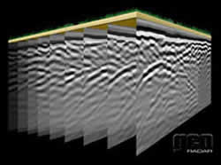
The parallel 2D profiles juxtaposed in sequence to produce a 3D cube

The profile after migration and Kirhoff's transformation – representing the layout of pipes
The animation showing subsequent profiles. The ostensible motion of pipes results from the shape of ground and its properties, but, most of all, from the diagonal route of pipes in relation to the direction of profiles.

The structure section with the effect of transparency shows the precise route of 3three pipes. The pipe on the left is made of iron (the strongest signal), while the pipes on the right are smaller and probably made of PCV (weaker signal).